Ajile DepthScan 3D 成像仪搭配 PolyWorks 的机器人搭载式三维检测方案
Robot-Mounted 3D Inspection Combines DepthScan Imaging with PolyWorks Measurement
Ajile DepthScan 3D 成像仪与 PolyWorks 检测软件组合成机器人搭载式三维检测方案,由机器人把成像仪送到编程位置,从多个视角采集复杂零件几何特征,再将点云与 CAD 模型和工程图纸比对完成尺寸测量。该方案针对自动光学检测的一个关键难题:盲孔、螺栓孔和侧面等特征需要接近法向的视角才能获得可用的测量数据,机器人携带成像仪绕零件移动即可从所需视角采集这些特征。各次采集在机器人坐标系中配准,合并为表示被测零件的全彩点云,随后在 PolyWorks 中依据 CAD 模型和图纸定义的 feature、基准和公差评估尺寸符合性,输出偏差值和每项控制项的合格/不合格状态。检测流程从 Ajile Calibrate 引导的手眼标定开始,确定成像仪相对机器人工具法兰的位置与姿态,再用基准件验证测量单元;机器人在每个编程检测位置发出到位信号后成像系统采集视图。检测规划在 PolyWorks 中基于 CAD 模型和图纸完成,可保存为模板复用;生产时操作员通过 Ajile Inspect 选择零件、输入序列号并启动检测循环,结果按单个零件保存并可导出批量报告。在机器人单元上验证过的观察位置还可移植到围绕零件的固定 Multi-DepthScan 框架,多台成像仪同时采集以缩短数据获取时间,形成从柔性机器人检测到快速固定单元测量的路径。
Robot-mounted 3D inspection can automate the capture of complex part geometry while integrating measurement and reporting into established quality workflows. A solution combining the Ajile DepthScan 3D Imager with PolyWorks inspection software uses robot positioning to capture features from multiple viewing angles, then measures the resulting point cloud against CAD models and engineering drawings.
The approach addresses a key challenge in automated optical inspection: ensuring that critical features are captured from suitable angles to support reliable dimensional measurement. Bores, bolt holes and side faces, for example, may require near-normal viewing angles to obtain useful measurement data.
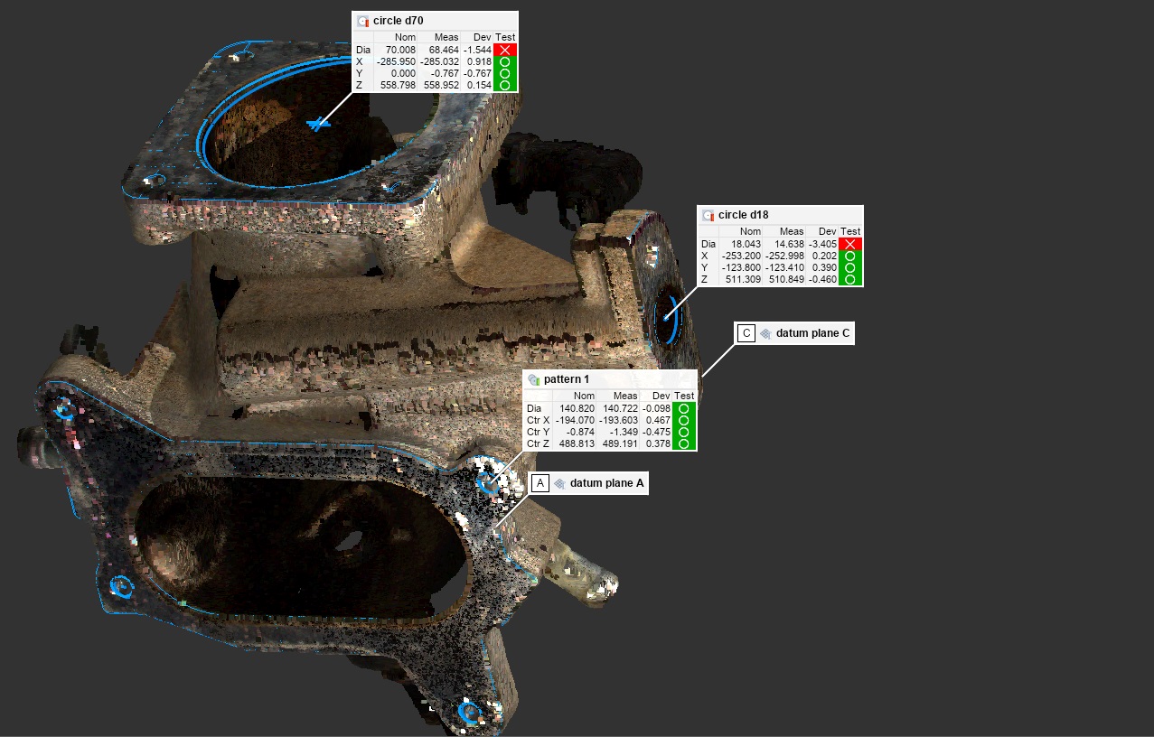
By carrying a DepthScan 3D Imager to programmed positions around a component, the robot can capture these features from the required viewpoints. The individual captures are registered in the robot’s coordinate frame and combined into a full-colour point cloud representing the inspected part.
The resulting data is then processed in PolyWorks, where features, datums and tolerances defined from the CAD model and drawing are used to evaluate dimensional conformity. The software generates measurement results showing deviations from nominal values and pass-or-fail status for each specified control.
From Cell Calibration to Automated Inspection
 The inspection workflow begins with calibration of the robot-mounted imaging system. Ajile Calibrate guides the user through a hand-eye calibration procedure to establish the position and orientation of the imager relative to the robot’s tool flange. A reference artefact is then used to verify the measurement cell before production inspection begins.
The robot’s movement programme, positioning and safety arrangements are configured separately. At each programmed inspection position, the robot signals that it has arrived, allowing the imaging system to capture the required view before the robot moves to the next position.
Inspection planning is completed in PolyWorks using the component’s CAD model and drawing. Existing CAD-based measurement plans can provide a starting point, although scan-based inspection requires the feature extraction settings to be configured for point-cloud data. Once established, the inspection plan can be saved as a template and reused for subsequent components.
During production, operators use Ajile Inspect to select the part, enter its serial number and initiate the inspection cycle. The robot executes the programmed sequence of views, after which PolyWorks evaluates the captured data and displays the results, highlighting controls that fall outside their specified limits.
Results are saved against individual parts and can be exported in batch reports, providing a record of inspection outcomes for quality documentation and traceability.
From Robot Programming to Fixed Inspection Cells
Robot-mounted inspection also provides a route towards higher-throughput automated measurement. Once the required viewing positions have been established and validated on the robot cell, the same inspection geometry can be implemented in a fixed Multi-DepthScan frame surrounding the component.
In this configuration, multiple imagers can capture the part simultaneously, reducing the time required to acquire the data compared with sequential robot positioning.
The robot cell is therefore used to develop and validate the inspection approach, while a fixed multi-imager arrangement offers a potential route to shorter cycle times in production environments where inspection speed is critical.
By combining programmable optical data capture with CAD-based dimensional evaluation, the workflow connects robotic inspection with established metrology software and reporting practices. It provides a path from flexible, robot-guided inspection during process development to more rapid, fixed-cell measurement for production applications.
For more information: www.ajile.ca


来源:Metrology News · 测量与质量控制 · metrology.news